
Like anything worth creating, solidifying the process of a project is key to success. Often, the ambitious work of aspiring music producers can get bogged down from a lack of organization. Projects can bloat into dozens of unnamed tracks processed with reckless abandon, and audio and MIDI clips get chopped and sliced into a charcuturie board of chaotic (un)organization.
For the fever-pitched producer in a flow state, this chaos can be managed during the session (to an extent). But what if they were to step away from the project and come back days later? What if they want to collaborate with another producer? It might take hours to untangle the intricate mismanagement of such a project.
In this article, we’ll be going over the core concepts of signal routing in audio production, discuss topics in both the analog and digital spaces, and suggest useful guidelines for the management and processing of a proper audio production. After reading this guide you should feel confident when organizing a session or when jumping back into a project—whether it’s been a few hours or a few years since you’ve last seen it.
What Is Audio Routing?
Routing is the determination of the path of an audio signal from its source (a microphone or instrument) to its destination (speakers or a recording device) from input to output, or I/O. This can be as simple as point A to point B, or as intricate as A to B to C with A copied to D which goes to E … et cetera et cetera.
While the basics of routing can be quite simple, routing can become complex extremely quickly, especially when dealing with modern recording and mixing practices. Concepts like signal chains, parallel processing, and subgrouping can turn a signal diagram from a straight line into an intricate web—but don’t fret! Understanding these key concepts isn’t rocket science. Here’s some tips to help you get started.
Components of Routing
Audio routing is comprised of five basic components in this order:
Audio Source: Routing begins with an audio source—an instrument, microphone, or any audio playback device, connected to an input.
Input: The source sends a signal to an input, which is typically a line or microphone input found on a device like a mixer or audio interface, or the digital inputs on a track in a DAW.
Processing: Oftentimes, engineers will want to alter a signal with processing—this can be EQ, compression, reverb, or any kind of outboard gear or digital plug-in that changes the nature of the original signal. This can be done in a multitude of ways.
Output: The output is the point in which the audio signal is sent out of whatever device or system you’re using. This will be the point at which you’ll send the audio to the next step, or where it will be heard and/or recorded.
Destination: The destination is where you hear or record the audio. These can be headphones, speakers, or a recording device like a tape machine or a print track on your DAW.
Advanced Routing Components
There are a few other stages an audio signal can be routed with or through, more often found in professional recording environments. If you’re working entirely within a DAW, you can jump to the next section of this article, but some of the concepts discussed in this section are useful to know (especially for simulated studio environments like Reason).
The Patchbay: A patchbay is the hub of a recording studio, connecting the inputs and outputs of all the studio’s gear like the telephone switchboards of yore.
A patchbay is a box with vertical pairs of connection points that signal can flow between—top is output and bottom is input (unless you’re a contrarian and want to make everyone upset). The rear of the bay is connected to a piece of audio equipment, and the front has two ports for routing signal to or from that gear.
The normalling of a patch point defines how the signal can be routed—it’s a useful thing to understand, even if you never encounter a patch bay.
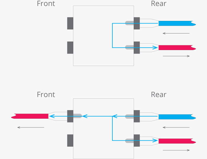
1. Full-Normal is when the rear panel connections are linked but are broken when a patch cable is inserted into either of the front panel ports. This is commonly used for serial processing.
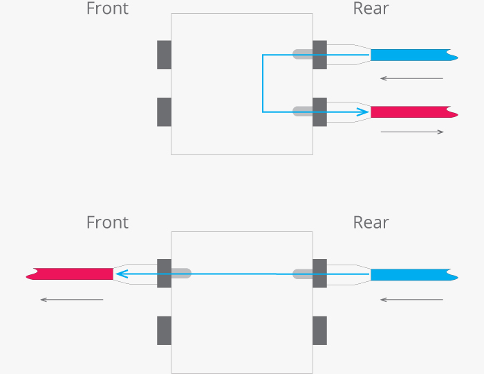
2. Half-Normal also has the rear connections linked. However, inserting a patch cable into the top (out) does not break the link, while connecting to the bottom (in) does. The signal is “split,” with one split going to a new location via patch cable, and the other remaining on its original route through the back of the patchbay. This is perhaps the most commonly encountered patch point, and is commonly used for parallel processing (especially because you can “dead patch” the output connection to create a makeshift full-normal patch point)
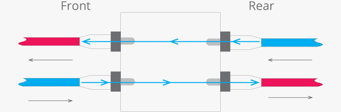
3. Non-Normal or Thru is when the rear connections are not linked at all, so all routing is done from the front panel. Thru can also be done when inserting cables in both the patch points of a half-normalled circuit.
The Channel Strip: Channel strips accept input from an audio source and are comprised of multiple components housed within one device—usually consisting of a preamplifer, equalizer, pan knob, and fader (some will include more). They often also include auxiliary sends, which we will discuss later. They can be standalone units or can be one of a series of units built into a mixing console.

Routing from channel strips can be quite flexible, usually offering multiple points in which the signal can be sent to the next stage. While every channel strip will have its own architecture, most are ordered as input gain -> dynamics/EQ -> aux sends -> pan -> fader (or fader -> pan), and will have at least these three tap points:
4. Post-Pan: Commonly the default setting of a track, the signal is sent after the pan-pot (often the final stage of the strip), meaning that left and right information will be sent to the destination.
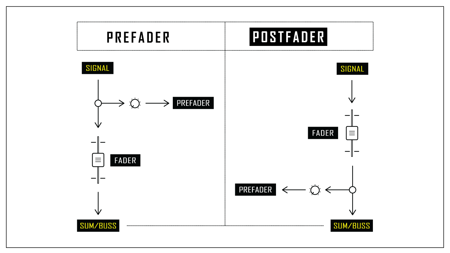
5. Post-Fader (AFL): Post-Fader (or “after fader listen”) sends the signal after the fader but before the pan pot. This means that the positioning of the faders will affect the level of signal leaving the channel strip, but the position of the pan-pot will not.
6. Pre-Fader (PFL): Pre-Fader (or “pre fader listen”) sends the signal before the fader, meaning the level of the signal sent from the strip disregards the position of the fader (the level is controlled only by the input gain on the preamp, the first stage). This is often used for monitor/headphone mixes for performers, dynamic processing inserts, and for other monitoring purposes.
Note: In a DAW, each audio channel/track acts like a channel strip would on a mixing console. This is not to be confused with “channel strip plug-ins” which are usually just a single plug-in with multiple functions that would be found on a real channel strip—this is done to emulate vintage mixing consoles.
Signal Flow Basics
Now that you have an idea of the multiple stages and places a signal can be routed to and from, let’s get into the specifics of signal flow, processing, and methodologies.
There are a few components and concepts to know when routing signal into an organized flow:
1. Audio Channel/Track: An audio channel is a path that holds a single audio signal (or more if its stereo or surround). This is the first stage where audio signals live before they are routed.
2. Send: A send copies the audio signal from a channel for routing to a different location and controls how much of that signal you want to send. This keeps the original audio signal intact while the copy is usually parallel processed or used for monitoring. Some hardware audio channels will have dedicated aux send rotary knobs on the channel strip, while DAWs will typically allow you to send signal from an audio track to another location via a bus or summing folder.
3. Insert: An insert is the place where you can use plug-ins or outboard gear to directly affect the signal in an audio channel—this is done pre-fader by default (with the exception of master output tracks). On a DAW, it’s as simple as putting a plug-in on the audio track itself. On hardware audio devices, it’s a single port that needs a y-split cable to send and receive signal from outboard gear.
4. Bus: A bus is a pipeline connection that signals are routed through, much like using a patch cable. However, a bus can carry multiple signals at once, so you can have any number of audio tracks routed and combined to a single destination.

5. Aux Track: An aux track (sometimes called aux return) is the destination of a bus. It’s an actual full audio track, so it can be manipulated and processed in any way an individual audio track can be (Auxes can also be bussed to other auxes and so on). They often house either a sub mix or are used for parallel processing for effects like reverb and delay. Aux tracks are then routed to another aux track or to the master output.

6. Master Output/Stereo Out: The master output (or master track, master bus, stereo out, etc.) is the final stage of the signal flow—all tracks are summed (typically to stereo) at this point, ready to be recorded onto tape or printed onto a master track. Master outs are unique from audio channels because their inserts are usually post-fader as opposed to pre-fader.
Note: There is much confusion regarding the nomenclature of “bus,” “aux,” and “send.” This article has shared the textbook definition of these concepts, but in practice, these words are often used interchangeably—some people will call a submix a group bus, or an aux track an effects bus, and vice versa. Don’t get caught up in the nomenclature, just be clear about what your routing is actually doing.
Routing Methods
There are many types of routing methods, but these four are the common in both digital and analog signal routing:
1. Direct: With direct routing, an audio signal is sent directly from the source to the destination without any extra steps along the way. Simple point A to point B.
2. Serial: Serial routing done in a chain, with I/O and effects applied one after another—point A to B to C and so on. The original signal is sent through a series of devices, changing the nature of the signal by the time it reaches the output. Using inserts is an example of serial processing.
3. Parallel: Parallel processing is done by splitting or copying an audio signal and sending it to another channel(s)—this is routed via a bus and is controlled via an aux track. This way, multiple instances of a signal can be processed in different ways and then mixed. This is useful for temporal effects like reverb and delay, giving you more control over the original sound.
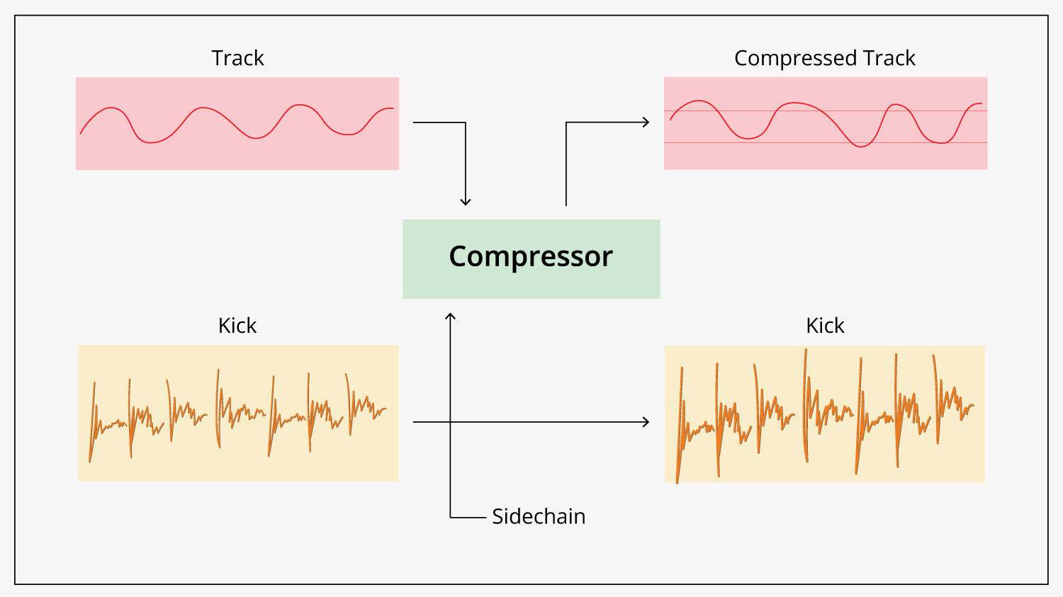
4. Sidechain: Sidechaining is a routing technique where an effect on one signal is triggered on or off by a condition of another signal (often volume or frequency). It’s often used to create a pumping effect via sidechain compression but can be used in a variety of ways to trigger creative or restorative effects.
Keep in mind that a single audio signal can be routed with any combination of these methods. Now, let’s look at an example of how routing might look in a typical session.
Routing Tutorial: Creating a Mix Template in a DAW
A great way to begin the practice of properly organized routing is by creating a template for your DAW. Of course, depending on what you’re trying to achieve, your workflow, and your personal preference, this can be done in any number of ways. I’ll illustrate a typical and simple DAW template so you can have an idea of where to start.
It’s worth mentioning that there are plenty of templates for all kinds of DAWs that you can download from the internet—but it’s truly worth making one yourself if you’re just beginning to understand routing when using a DAW. I strongly recommend it.
Step 1: Categorize Your Tracks
Most music productions consist of drums, bass/guitars/keys and vocals, as well as any effects added to them like reverb and delay. The first thing you should do when creating a template is delineate all your tracks into these categories—color code them, name them, sort them, and do whatever else that will make it easiest for you.
Some DAWs like Pro Tools allow you to place tracks into groups, allowing you to control the parameters of every track simultaneously.
Step 2: Create Submixes to Gain Hierarchical Control
When you have your tracks laid out in proper categories, the next step is to route the tracks from each category into their own submix. There should be a single stereo track all the drum tracks will be routed to, another for vocals, and so on. Name them “Drum mix,” “Vocal mix,” and so on.
Each audio channel should have a direct output send that will send the signal to its corresponding individual stereo aux track. Do not use a typical bus (parallel processing) as we’re not trying to copy the signal to the submix; we’re trying to send the entire thing. Some DAWs (like Logic) allow routing via folder and summing stacks. You can do what you want but keep your template consistent.
This is the first step to achieving a hierarchy of control. Each individual track can have its own processing, EQ, panning, or what have you, but with submixes, you can process, mute, pan, and otherwise control entire sections of the music in one broad stroke. Mute all the guitars with one click, put EQ on vocal submix that will be consistent throughout, glue together the drums with compression—all done more efficiently at the submix level.
Step 3: Create Effects Sums (FX sends) for Parallel Processing
Certain effects like reverb and delay will benefit from parallel processing. You can route individual tracks or entire submixes to an FX aux track via a bus. This is useful because you can EQ or process just the effects of a signal without affecting the original. It’s a common practice to send all the FX aux tracks to an FX sum submix, so you can control how wet or dry the mix via a single control.
Step 4: Route Everything to the Master Out
Once everything is lined up and in order, make sure that all the submixes and the effects sum are routed to the master out, or master bus. Individual audio tracks can also be (and are by default) sent directly to the master sum, but keeping things in order is a great way to start your template.
Step 5: Print the Master Output to a Print Track
While you can simply bounce or export the audio track right from the taskbar in a DAW, its common practice in professional audio to route the master output to a separate stereo “print track.” Essentially, you arm the print track to record and then make a full pass of the audio project. This allows for monitoring of the project for any technical errors or mistakes made during the playback as well as create lead-in and lead-out sections of silence for mastering engineers.

Proper routing saves time and allows for more creative control over any project. This is just one way to route an audio project. As time goes on and with practice, you’ll find a routing method that meshes with your personal preference and taste.
We hope this guide is a helpful reference for you as you get started in your audio journey. Feel free to reach out to out team of experts at B&H if you have any questions or need any help setting up your studio and your session templates.
