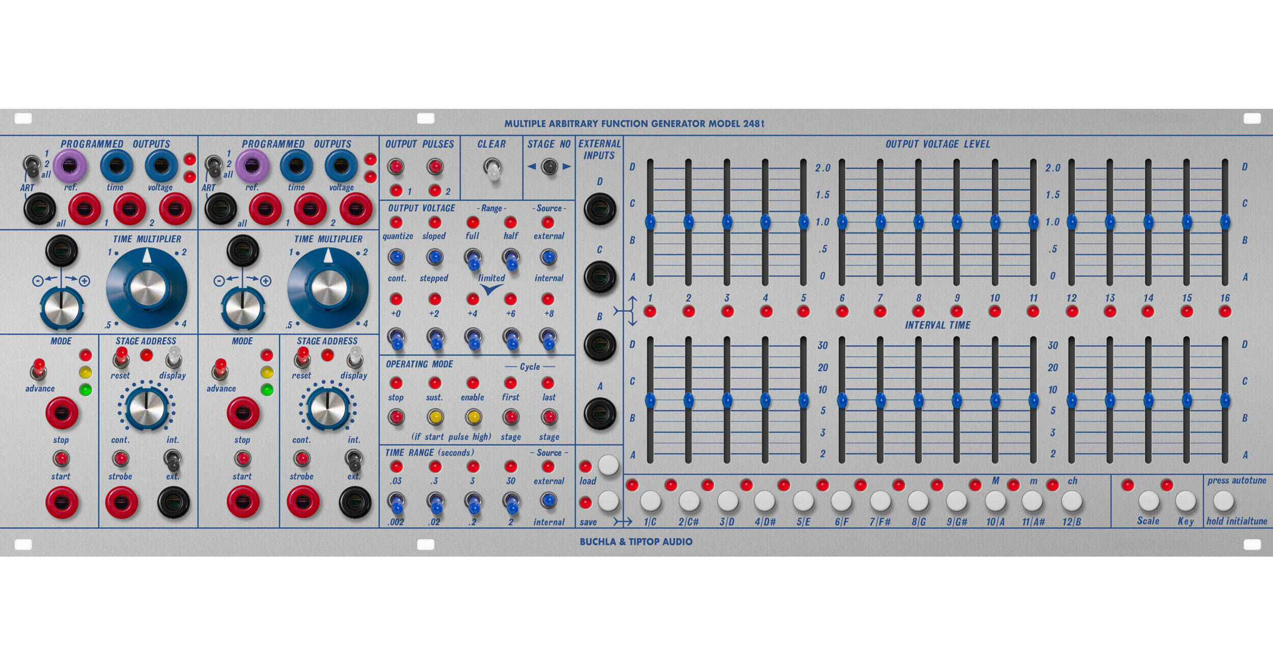
Shape your sounds with the Tiptop Audio Buchla Model 248t MARF Multiple Arbitrary Function Module, a sequencer/envelope generator that embodies the true aesthetic of West Coast syntheses. It features 16 dedicated output voltages, 16 interval time sliders, and signal generation and processing functionality.
The 248t moves beyond typical sequencer/envelope generator constraints for open-ended voltage output and an unparalleled amount of dynamic musical control. With 16 or 32 addressable storage locations, you can produce any desired asynchronous outputs with their own time scales and phase relationships as desired.
3 Main Sections
The two Function Generators make the module arbitrary. They work independently of each other and can access the 16 stages in multiple different ways. The Programming Section works in conjunction with the Output Voltage & Time Sliders to make modifications to each stage’s voltage level, length of time, and how each stage operates amongst the rest of the stages.
Output Voltage Sliders
Output Voltages and Time Sliders
- Output Voltage Level: The top row of sliders sets the main output voltage level in conjunction with the Output Voltage programming section per stage. Alternatively, they select which of the external input voltages (A, B, C, D) are passed through the output voltage modifier programming and out through the voltage output jacks.
- Stages: The 16 LEDs along the middle represent the 16 stages, and light up when they are advanced and displayed by the FGs, or when using the Stage Number edit switch.
- Interval Time: The lower row of sliders sets the interval time of each stage in conjunction with the Time Range programming section. The default time range is set from 2 seconds at the bottom of the slider to 30 seconds at the top of the slider, as indicated on the panel. The sliders also output a voltage based on their settings at the Time output on the FGs.
Presets and Quantized Structures
- The row of buttons under the 32 Voltage and Time sliders allow for storing and recalling 12 Presets with an alternate function of selecting the scale and key for the stages with Quantize enabled. In addition, there is a button for sending an Auto-Tune message to ART equipped oscillators.
- Loading a preset: press the Load button and then one of the buttons labeled 1 to 12. The settings in that memory location are immediately recalled for all 16 stages. Note that the sliders values are replaced by saved values and the sliders are only active once they have moved past the stored value.
- Saving a preset: press the Save button and then one of the buttons 1 to 12. All stage settings including the slider positions are saved to nonvolatile memory.
- Changing Key: Press the Key button and then one of the 12 Keys (C to B).
- Changing Scale: Press the Scale button and select Major (10), Minor (11) or Chromatic (12).
- Auto Tuning: Pressing the Autotune switch once will send the tuning message to both ART outputs. Holding the switch for a few seconds sends the Initial Tune message.
Voltage Programming Modifiers
- Quantize/Continuous: A three-position momentary switch that defaults to the unquantized continuous voltage setting. Pressing up quantizes the voltage to a one-volt-per-octave scale. Pressing down removes quantization.
- Sloped/Stepped: A three-position momentary switch that defaults to stepped mode. Pressing up adds slew time to the stage. The slew time is based on the interval time of the stage. Pressing down removes the slope.
- Range—Full Range / Half Range / Limited: A momentary switch that defaults to full range, meaning the output voltage sliders produce 0–10V. Half Range cuts the output to 0 to 5V, which approximates the original 5 octave range and makes it easier to dial in exact pitch compared to Full. The five limited range switches restrict the slider to a 2 volt span with octave offsets. The original module was only one octave, while the Eurorack 1V/octave range allows for two.
- Source - External/Internal (Voltage): This three-position momentary switch defaults to internal mode, meaning the stage’s slider and modifiers determine the output voltage. In external mode, CV sources patched into inputs A, B, C, or D are routed through the voltage modifiers, and the slider selects, which external inputs is active.
Operatin gMode Modifiers
- Stop (three-position momentary switch): Pressing up adds a stop modifier to the stage. When a Function Generator reaches a stop stage, it will not advance until a start pulse is received. The stop stage still respects its interval time.
- Sustain (three-position momentary switch): Pressing up adds the sustain modifier. When a high pulse (gate) is present at the start input, the Function Generator holds on that stage for as long as the pulse remains high.
- Enable (three-position momentary switch): Pressing up adds an enable modifier. The Function Generator pauses on the stage until a voltage above 5V is applied to the start input.
- Cycle—First/Last (three-position momentary switch): These modifiers define the start and end points of a cycle. Function Generators begin at the first marked stage and loop back to it after reaching the last-marked stage.
Time Programming
- Time Range Switches: Four momentary switches select the interval time range, from very fast (0.002 seconds) to very slow (up to 2 minutes).
- Source—External/Internal (Time): Three-position momentary switch. Internal mode uses the sliders and time range switches to define timing. External mode allows CV sources patched into A, B, C, or D to control the interval time.
Function Generators
Outputs and Indicators
- ART Output (black jack): Outputs a digital signal for precise pitch based on the output voltage slider and applied modifiers. Plug into the 259t ART input and set the 259t to ART mode.
- On the MARF, use the switch above the ART outputs to select the gate source: Pulse 1, Pulse 2, or pulses on all stages (ALL).
- When using ART to control an oscillator’s pitch, the gate for the envelope can be taken either directly from the oscillator or from the MARF itself, providing two different envelope response options. These gates are not identical when modifiers are used.
- Voltage Output (blue jack): Outputs CV based on the output voltage slider and applied modifiers. The output is 1V/oct when a stage modifier is set to Quantized.
- Time Output (blue jack): Outputs a CV proportional to the interval time slider. Can be used as a second CV source without affecting the time when the TIME RANGE modifier Source is set to External.
- Programmed pulse outputs (red jacks): Two outputs provide gates on stages programmed with Pulse 1 or Pulse 2 switches.
- Output LEDs (two red LEDs): Display the gate outputs.
- Reference Output (purple jack): Outputs a downward ramp spanning the interval time of the stage. Useful for driving a 292t LPG directly without an envelope.
- All Pulses Output (red jack): Outputs a pulse each time a new stage is addressed. Useful as a clock source for other devices.
Function Generator Controls
Mode
- Advance: Manually advances the Function Generator to the next stage.
- Start / Stop: Controls the internal clock manually or via pulse inputs.
- Status LEDs: Three LEDs indicate the clock state:
- Green—Run: Internal clock is running and advancing stages.
- Yellow—Hold: Clock advance is interrupted. This occurs when: A stage contains a Sustain or Enable condition and is waiting.
- for the required Start input condition.
- Red—Stop: Clock is halted by:
- Stop control or Stop pulse.
- Programmed Stop stage.
- Stage Address set to Continuous.
Stage Address
- Reset two-position momentary switch Returns the Function Generator to the first programmed stage. If no stage is programmed as First, the generator resets to Stage 1.
- Display two-position momentary switch Shows the current stage position without interrupting operation.
- Display LED Indicates which Function Generator is currently selected for Display. Only one Display LED is active at a time.
- Cont/Strobe three-position switch (momentary down, latching center and up) continuously sweeps through stages using the Address control and stops the internal clock.
- Pressing Strobe loads the stage corresponding to the current Stage Address value.
- Internal and External two-position latching switch Seletcs whether stage position is controlled by the knob or by external voltage.
Time Multiplier
A global time multiplier knob and CV attenuverter allow stage times to be scaled from half-time to four times longer
External Inputs
Four external CV input jacks allow external voltages to be used either to control timing or to be processed through the output voltage modifiers. If a stage's time range source is set to external and no CV is present, the interval time defaults to the fastest value of the selected range.
Eurorack Ready
- 52 HP Eurorack format module
- Maximum depth: 2" (52mm)
- Includes power ribbon cable with Eurorack power headers
- Power consumption: +12V: 360mA, -12V: 350mA