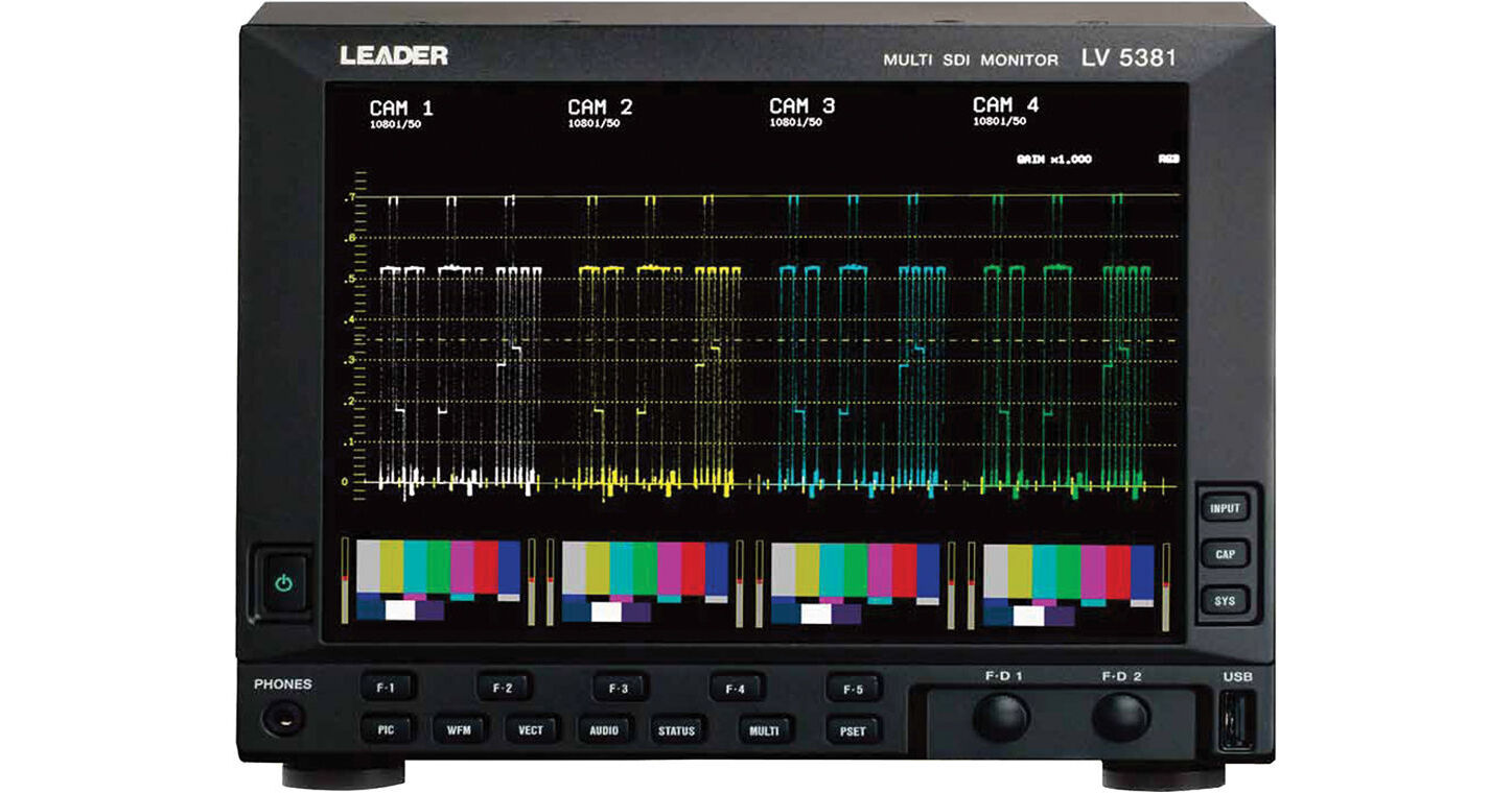
| Audio Playback |
|
| Compliant Standards | SMPTE - 299 M (HD-SDI)
SMPTE - 272 M (SD-SDI) |
| Quantization | 24 bits |
| Clock Generation | Generated from the video clock |
| Synchronization | All audio channels must be synchronized to the video clock |
| Input/Output Connectors |
|
| SDI Input | Input connectors - 4 BNC connectors (channels A, B, C, and D) |
| SDI Output | Output connectors - 2 BNC connectors |
| Output Signal | SDI signal selected from channel A or B is reclocked and generated
SDI signal selected from channel C or D is reclocked and generated |
| Output Impedance | 75 ohms |
| Output Voltage | 800 mVp-p ± 10% |
| Input/Output Return Loss | ≥ 15 dB for 5 MHz to the serial clock frequency |
| External Sync Input |
|
| Input Signal | Tri-level sync or NTSC/PAL black burst signal |
| Input Connectors | 2 BNC connectors |
| Input Impedance | 15 k ohms passive loop-through |
| Input Return Loss | ≥ 30 dB for 50 kHz to 30 MHz into 75 ohms |
| Maximum Input Voltage | ±5 V (DC + peak AC) |
| Headphone Output |
|
| Output Signal | Extracts and transmits the audio signal embedded in an SDI signal |
| Output Channels | Specified AES/EBU pair |
| Sampling Frequency | Only 48 kHz is supported |
| Output Connector | 1 stereo miniature jack |
| Volume Control | Configured from the menu |
| Power Output | 50 mW maximum (with 16 ohms load resistance) |
| Control Connectors |
|
| USB Port | USB 2.0 |
| Clip Splitting | Only supports USB memory devices |
| LCD |
|
| LCD type | 8.4" color TFT |
| Display Format | XGA |
| Resolution | 1024 x 768 |
| Backlight/Brightness | 32 levels |
| Auto Shutoff | Time to turn off the LCD can be set |
| Screen Capture |
|
| Screen Capture | Captures the screen to an image file (only one screen capture is stored in internal memory) |
| Clip Splitting | Internal memory (RAM) and USB memory |
| Data Output | Screen captures can be saved as bitmap files to USB memory |
| Data Inputs | Data saved to USB memory can be loaded and displayed on the LV 5381 |
| Preset Mode | Comprehensive preset, display mode preset |
| Waveform Display |
|
| Simultaneous Input Mode Display Format | Mixed, tiled, aligned |
| Display Mode | Overlay, parade |
| Overlay | Overlays component signals |
| Parade | Displays component signals side by side |
| Blanking Period | H and V blanking periods can be displayed or hidden |
| RGB Conversion | Converts a Y,CB,CR signal into an RGB signal and displays the result |
| Pseudo-composite Display | Artificially converts a component signal into a composite signal |
| Channel Assignment | Displayed in GBR or RGB order (selectable when RGB conversion is enabled) |
| Line Select | Displays the selected line |
| Gain | x1, x5
Variable gain - x0.2 to x2.0 |
| Filter | Flat, low pass |
| Waveform Display Accuracy |
|
| Amplitude Accuracy | ±0.5% |
| HD-SDI Input | Y signal - ±0.5% for 1 to 30 MHz
CBCR signal - ±0.5% for 0.5 to 15 MHz
Low-pass attenuation - ≥ 20 dB (at 20 MHz) |
| SD-SDI Input | Y signal - ±0.5% for 1 to 5.75 MHz
CBCR signal - ±0.5% for 0.5 to 2.75 MHz
Low-pass attenuation - ≥ 20 dB (at 3.8 MHz) |
| Scale | Type - % scale, V scale, decimal scale, hexadecimal scale |
| Display Colors | 7 colors |
| Thumbnail Display | Picture, audio level meter |
| Vectorscope Display |
|
| Simultaneous Input Mode Display Format | Mixed, tiled |
| Blanking Interval | Masked |
| Pseudo-composite Display | Artificially converts a component signal into a composite signal |
| Line Select | Displays the selected line |
| Gain | x1, x5, IQ-MAG
Variable gain - x0.2 to x2.0 |
| Amplitude Accuracy | ±0.5 % |
| Scale | Type - ITU-R BT.601, ITU-R BT.709, AUTO |
| Setting the Color Bar Saturation | 75%, 100% |
| Display Colors | 7 colors |
| Thumbnail Display | Picture, audio level meter |
| 5 Bar Display |
|
| Simultaneous Input Mode Display Format | Tiled only |
| Bar Display | Displays the peak levels of Y, R, G, B and composite |
| Channel Assignment | RGB, GBR |
| Scale | mV, % |
| Error Level | Based on the gamut error, composite gamut error, and luminance error thresholds |
| Picture Display |
|
| Simultaneous Input Mode Display Format | Mixed, tiled |
| Quantization | 8 bits |
| Color Temperature | 6500° K (6226.85° C), 9300 K (9026.85° C) |
| Image Quality Adjustment | Brightness, contrast, chroma gain, RGB gain, RGB bias, aperture |
| Display Sizes | Fit, full frame, real, 4:3 full screen |
| Color | R, G, B can be turned off separately, Chroma off |
| Frame Rate | The frame rate is converted and displayed using the internal sync signal |
| Aspect Display Marker | HD-SDI - 4:3, 13:9, 14:9, 2.39:1
SD-SDI - 13:9, 14:9, 16:9 |
| Line Select | Marks the selected line |
| Gamut Error Display | Displays gamut error locations over the picture |
| Thumbnail Display | Video signal waveform, audio level meter |
| Error Count Display |
|
| Function | Used to count the video, audio, and gamut errors |
| Video Error Display | Counts CRC (HD-SDI) and EDH (SD-SDI) errors |
| Audio Error Display | Counts embedded audio BCH (HD-SDI) and channel status bit CRC errors |
| Gamut Error Display | Upper limit - 90.8 to 109.4%
Lower limit - -7.2 to 6.1% |
| Composite Gamut Error | Upper limit - 90.0 to 135%
Lower limit - -40.0 to 20.0% |
| Error Count | Up to 999,999 errors can be counted separately for video, audio, and gamut |
| Count Period | One count per field |
| Current Time Display | The time based on the internal clock |
| Elapsed Time Display | The elapsed time since the error count was cleared |
| Other Display Settings |
|
| Input Information Display | Input channel, ID, OFF |
| Time Code | LTC, VITC, OFF |
| Format Display | The format can be displayed when an SDI signal is detected |
| Front Panel |
|
| Key LEDs | All the keys are dimly back-lit, and the selected key is lit more brightly |
| Environmental Conditions |
|
| Operating Temperature Range | 32 - 104° F (0 - 40° C) |
| Power Requirements | 10 to 18 VDC, 46 W maximum |
| Dimensions | 8.5 x 6.88 x 3.38" (215 x 176 x 111 mm) |
| Weight | 4.85 lb (2.2 kg) |